
Ever walked into a room and wished you could turn the lights on or off from two different spots? That's the magic of a 3-way switch system, a really handy setup in many homes. Yet, for many folks, the idea of wiring one can feel a bit like trying to solve a puzzle with missing pieces. You know, it's almost like looking at a complex map without a legend, which can be pretty frustrating, to say the least.
This kind of electrical arrangement, where you control a single light fixture from two separate locations, brings a lot of ease to daily living. Think about a long hallway, a stairway, or even a large living area; being able to flip the lights on as you enter and off as you leave, regardless of which entrance you use, is definitely a big convenience. So, understanding how these systems work is more than just a technical exercise; it's about making your home more functional.
Learning about the wire diagram of a 3-way switch doesn't have to be a source of stress, though. In fact, with a clear picture and a few simple explanations, you can actually grasp the fundamental ideas pretty quickly. We'll break down what each wire does, how they connect, and what to watch out for, giving you a better handle on this common household electrical task. It's about getting a firm grasp on the physical wires that carry electricity, which is quite different, for instance, from Wire, the secure communication and collaboration app trusted by millions worldwide, which uses digital signals, as a matter of fact.
Table of Contents
- What Exactly is a 3-Way Switch?
- The Wires You'll Encounter
- Tools and Safety First
- Understanding the Basic 3-Way Switch Diagram
- Common Challenges and Tips
- When to Call a Pro
- Frequently Asked Questions About 3-Way Switches
What Exactly is a 3-Way Switch?
A 3-way switch is a specific kind of electrical switch that lets you control a single light fixture from two distinct spots. Unlike a standard on/off switch, which only has two terminals for wires plus a ground, a 3-way switch has three terminals for wires, plus a ground screw. This extra terminal is what makes the two-location control possible, you know.
How It Differs from a Regular Switch
Think of a regular light switch as a simple gate: it's either open or closed, letting electricity flow or stopping it. A 3-way switch, however, is a bit more like a railway switch. It directs the electrical current along one of two paths. When you flip the switch, it doesn't just turn the power on or off; it changes which path the electricity takes to get to the next switch or the light, so that's a key difference.
A typical single-pole switch, which is what most people are familiar with, has two brass-colored screw terminals and one green or bare copper ground screw. A 3-way switch, on the other hand, usually has one dark-colored or "common" screw terminal, two lighter-colored or "traveler" screw terminals, and a green or bare copper ground screw. This is that extra complexity that makes it so interesting.
Why We Use Them
We typically use 3-way switches for convenience and safety. Imagine walking up a flight of stairs in the dark. With a 3-way setup, you can turn on the light at the bottom, climb the stairs safely, and then turn the light off at the top. This avoids having to walk back down just to hit the switch. It's really about making spaces more user-friendly, and that's a big deal for homes, you know.
They're also common in large rooms with multiple entryways, long hallways, or even in outdoor lighting setups where you might want control from inside and outside your home. The aim is to provide access to the light control wherever it's most practical, which can be a real time-saver, actually.
The Wires You'll Encounter
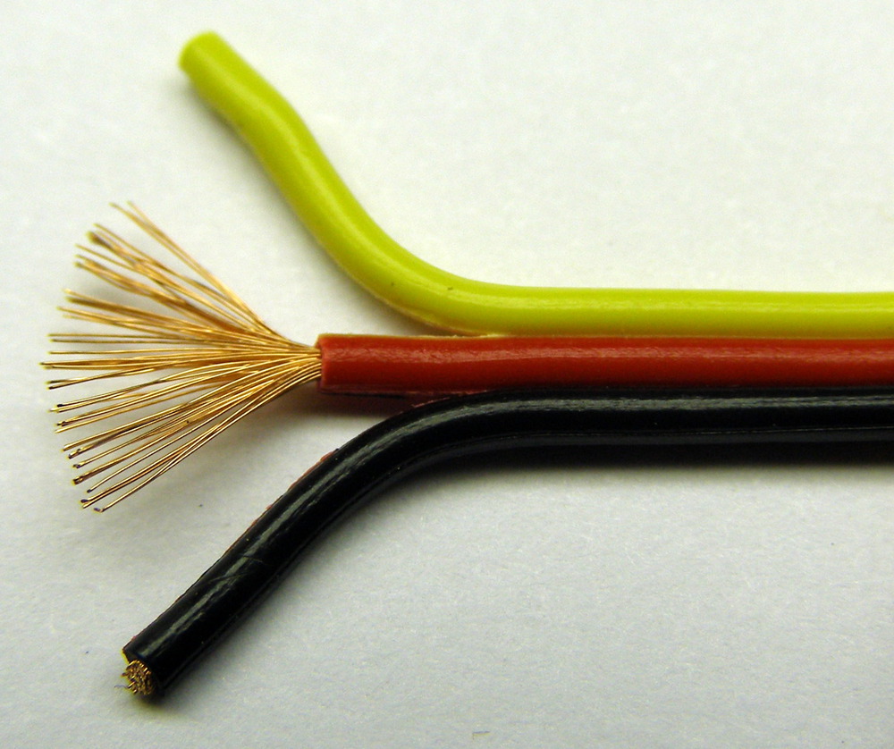
Before you even look at a wire diagram of a 3-way switch, it's good to know what types of wires you'll find in your electrical box. Each wire has a specific job, and understanding their roles is pretty important for a safe and correct installation. These are the physical wires that conduct electricity, very different from the concept of "Wire" as an encrypted communication platform, which operates on digital signals, as a matter of fact. Wires, in this context, are the actual metal strands or rods that bear electrical loads and transmit signals, typically found within electrical cables, as I was saying.
Hot Wire (Line)
The hot wire, also called the "line" wire, is the one that brings electrical current from your circuit breaker panel. It's typically black, and it's always "live" with power unless the circuit breaker is off. This wire connects to the common terminal on one of your 3-way switches, usually the one receiving power directly from the source. It's the starting point for the electrical flow, you know.
Identifying this wire correctly is really important for safety. A non-contact voltage tester can help you confirm which wire is hot even when the switch is disconnected. This step should never be skipped, honestly.
Load Wire
The load wire carries power from the 3-way switch system to the light fixture itself. It's also usually black, but its job is to deliver the power that actually turns on the light. This wire connects to the common terminal on the other 3-way switch, the one that sends power directly to the light fixture. It's the final leg of the journey for the electricity before it lights up your room, you know.
Sometimes, this wire might be red, especially in certain cable types, so color isn't always the only indicator. Tracing its path back to the light fixture is a good way to be sure, in a way.
Traveler Wires
These are the wires that connect the two 3-way switches to each other. There are always two traveler wires in a 3-way switch setup. They're typically black and red, or sometimes two black wires, but they always run together in a single cable. These wires carry the power back and forth between the two switches, allowing either switch to control the light. They connect to the lighter-colored "traveler" terminals on both switches, so they're pretty key.
The traveler wires don't directly connect to the power source or the light fixture; they just create the communication path between the two switches. This is where the "magic" of controlling a light from two spots really happens, you know.
Ground Wire
The ground wire is a safety wire, usually bare copper or green insulated. Its job is to provide a safe path for electricity to go if there's a fault or short circuit, preventing electrical shocks and fires. It connects to the green screw terminal on both switches and to the metal electrical box, if it's a metal box. This wire is absolutely essential for your safety, as a matter of fact.
Always make sure the ground wire is properly connected. It's a critical safety feature that protects you and your home, and that's just a little something you should never overlook.
Neutral Wire
The neutral wire completes the electrical circuit, carrying electricity back to the main electrical panel. It's typically white. While 3-way switches themselves don't always directly connect to the neutral wire (unless they have smart features or indicators), the neutral wire is always present in the electrical box and is essential for the light fixture to work. It's the return path for the current, you know.
Modern electrical codes often require a neutral wire in switch boxes, even if the switch itself doesn't use it. This is for future smart home devices that might need a neutral connection to function properly, so it's a good thing to be aware of.
Tools and Safety First
Before you even think about touching any wires, gathering the right tools and, more importantly, prioritizing safety is just absolutely necessary. Working with electricity can be dangerous if you're not careful, so you really want to be prepared, you know.
Essential Tools
You'll need a few basic tools for this project. A screwdriver set (both Phillips and flathead) is pretty obvious. Wire strippers are also a must for cleanly removing insulation without damaging the wire itself. A non-contact voltage tester is arguably your most important safety tool; it lets you check if a wire is live without touching it. You might also want a pair of needle-nose pliers for bending wires into loops for screw terminals. These are just some really helpful things to have on hand, in a way.
Having a good flashlight is also helpful, as you'll likely be working in areas where the power is off. A pair of work gloves can offer some protection, too. It's about having everything you need before you start, so you don't have to stop midway, you know.
Crucial Safety Steps
Safety is not something to take lightly when working with electricity. First and foremost, always, and I mean always, turn off the power at the circuit breaker before you do anything. Don't just flip the light switch off; go to your main electrical panel and turn off the breaker that controls the circuit you're working on. This is the single most important step, honestly.
After turning off the breaker, use your non-contact voltage tester to double-check that the wires are truly dead. Test every wire in the box, not just the ones you think are part of the circuit. It's better to be overly cautious than to risk a shock. Also, wear safety glasses to protect your eyes from any unexpected sparks or debris. Learn more about electrical safety on our site, it's a good idea.
Never work on wet surfaces or with wet hands. Water conducts electricity, and that's a really bad combination. If you're unsure about anything at all, it's always better to stop and get help from someone with more experience or a professional electrician. Your safety is worth more than saving a few bucks, you know.
Understanding the Basic 3-Way Switch Diagram
Now for the main event: how the wires connect. There are a few common ways to wire a 3-way switch system, but the most straightforward involves power coming into one switch box, and the light fixture being wired from the other switch box. We'll focus on this common method to give you a clear picture, you know.
Switch 1 (Power Source)
Imagine your first switch box, the one where the power comes in from your electrical panel. In this box, you'll have a cable with a black (hot), white (neutral), and bare copper (ground) wire. You'll also have a 3-wire cable (black, red, white, plus ground) going to the second switch. It's a bit like a junction point, in a way.
At Switch 1, the incoming black hot wire from the power source connects to the common terminal (the darker screw) on the 3-way switch. The black and red wires from the 3-wire cable (which are your travelers) connect to the two lighter-colored traveler terminals on the switch. The white neutral wires from both cables are typically connected together with a wire nut, as are the bare ground wires. This setup ensures power can travel between the switches, you know.
Switch 2 (Light Fixture)
Now, let's look at the second switch box, the one closer to the light fixture. In this box, you'll have the same 3-wire cable (black, red, white, plus ground) coming from Switch 1. You'll also have a 2-wire cable (black, white, plus ground) going up to the light fixture. This is where the circuit finally reaches its destination, you know.
At Switch 2, the black and red traveler wires from the 3-wire cable connect to the two lighter-colored traveler terminals on this 3-way switch. The white neutral wires from both the incoming 3-wire cable and the outgoing 2-wire cable (to the light) are connected together with a wire nut. The bare ground wires are also connected together and to the switch. The black wire from the 2-wire cable (to the light fixture) connects to the common terminal (the darker screw) on this 3-way switch. This is how the power gets sent up to the light, you know.
Step-by-Step Wiring Explanation
Let's walk through the connection process, assuming power is off at the breaker. First, at Switch 1, identify the incoming hot wire from the power source. Connect this to the common screw terminal of the first 3-way switch. Next, take the black and red wires from the 3-wire cable that goes to Switch 2. Connect these to the two traveler terminals on Switch 1. Make sure all ground wires are connected together and to the switch's ground screw. All neutral wires should be bundled and capped with a wire nut, as a matter of fact.
Moving to Switch 2, take the black and red traveler wires coming from Switch 1 and connect them to the two traveler terminals on the second 3-way switch. Identify the black wire that goes directly to your light fixture. Connect this wire to the common screw terminal on Switch 2. Again, ensure all ground wires are properly connected. The neutral wires from the cable coming from Switch 1 and the cable going to the light fixture should be connected together with a wire nut. This setup, arguably, is the most common way to do it, you know.
It's important to remember that the specific common terminal might be at the top or bottom of the switch, depending on the brand. Always check the switch's instructions or look for the darker-colored screw. A continuity tester can also be useful to confirm connections before you restore power. This careful approach helps ensure everything works as it should, you know.
Common Challenges and Tips
Even with a clear wire diagram of a 3-way switch, you might run into a few snags. Knowing what to look for can save you a lot of frustration and time. It's almost inevitable that you'll face a small challenge or two, so being ready for them is a good idea.
Troubleshooting Common Issues
One common problem is that the light only works from one switch, or not at all. This often means your common wire is misidentified or incorrectly connected. Double-check that the incoming hot wire is on the common terminal of the first switch and the wire going to the light fixture is on the common terminal of the second switch. Sometimes, people accidentally connect a traveler wire to the common terminal, which will cause issues, you know.
Another issue could be that the light flickers or doesn't turn on reliably. This might point to loose connections. Always make sure all wire nuts are tight and all screw terminals are snug. A loose connection can cause resistance, leading to poor performance or even overheating. It's a small detail that makes a big difference, honestly.
If you're using older wiring, you might not have a neutral wire in your switch box. This can be a problem for modern smart switches that often require a neutral connection to power their internal electronics. In such cases, you might need to run new wiring or choose a smart switch designed to work without a neutral. That's a bit of a tricky situation, sometimes.
Tips for Success
Before you disconnect any wires, take pictures of the existing setup. This can be a lifesaver if you get confused during the process. Label your wires clearly as you disconnect them—"incoming hot," "traveler 1," "traveler 2," "to light fixture," and so on. Masking tape and a marker work perfectly for this, you know.
Always test your circuit with a non-contact voltage tester before and after you think the power is off. Once you've completed the wiring, turn the power back on at the breaker and test both switches multiple times to ensure they operate correctly from both locations. It's a good habit to cycle them on and off a few times to confirm everything is working as it should, you know.
And remember, wires are physical conductors, often in the form of electrical cables, used for electricity and telecommunications signals. This is quite different from "Wire," the secure messenger app available on various operating systems like iOS, Android, macOS, Windows, Linux, and web browsers, which facilitates team collaboration. The physical wires you're working with here are about carrying electrical current safely, and understanding their function is key. Explore other home improvement guides on our site for more helpful information.
When to Call a Pro
While understanding the wire diagram of a 3-way switch can empower you, there are times when it's just plain smarter to call in a licensed electrician. If you feel uncomfortable at any point, or if the wiring in your home looks older, unusual, or simply too complicated, don't hesitate. Electrical work, when done incorrectly, can be dangerous, leading to shocks, fires, or damage to your home's electrical system. Your safety and the safety of your home are paramount, you know.
If you're dealing with aluminum wiring, knob-and-tube wiring, or if you're unsure about your home's electrical capacity, a professional can assess the situation safely. They have the experience and tools to handle complex scenarios and ensure everything meets local electrical codes. It's always a good idea to get a professional opinion when in doubt, honestly.


Detail Author:
- Name : Guido Goyette
- Username : parker.aron
- Email : raul.hansen@willms.net
- Birthdate : 1990-05-27
- Address : 8958 Rupert Knolls Suite 980 South Germaineburgh, WI 82860
- Phone : +1.551.706.4355
- Company : Cormier, Harber and Gaylord
- Job : Metal Fabricator
- Bio : Iste illum impedit eos itaque dolor. Quaerat ut consequatur id ut et. Illo occaecati est blanditiis aut non.
Socials
facebook:
- url : https://facebook.com/icie_dev
- username : icie_dev
- bio : Dolore dolorem quis expedita voluptatem iusto. Enim quidem et quia est.
- followers : 498
- following : 2611
instagram:
- url : https://instagram.com/willmsi
- username : willmsi
- bio : Est eveniet nostrum eum enim sit dolores. Sit qui et autem eaque vel. Et et tempora in non.
- followers : 2124
- following : 2638
